ARDUINO PROGRAMMING
- sjhyun20
- Nov 28, 2021
- 9 min read
For this individual work on input and output device, we used Tinkercad for our Arduino programming.
Tinkercad is a web-based simulation to develop and test Arduino code before we execute the code on the Arduino board.
We had four sections in this individual activity. Input devices: a. Interface Potentiometer Analog Input to Maker Uno board and measure its signal in serial monitor Arduino IDE, b. Interface a LDR to Maker Uno board and measure its signal in serial monitor Arduino IDE. Output devices: a. Interface 3 LEDs (Red, Yellow, Green) to Maker Uno and program it to perform something (fade or flash etc), b. Interface the DC motor to Maker Uno board and program it to on and off using push button on the board.
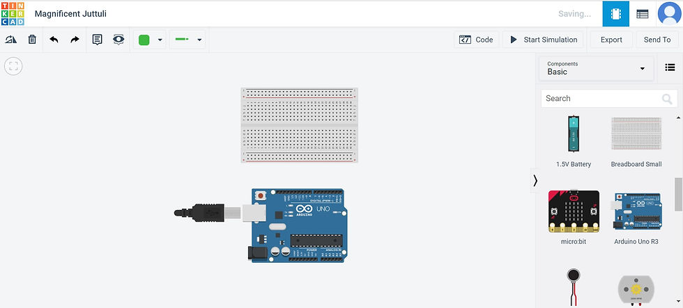
Before we execute the activities, we are going to step up the breadboard and Arduino Uno. We are setting it up in a way that it acts as a form of battery to the circuit.
First, drag the Arduino Uno and breadboard out and place them side-by-side.
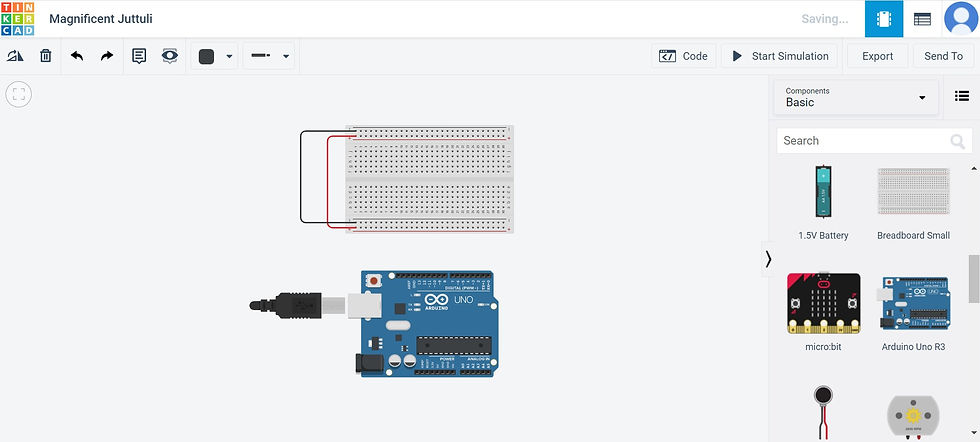
Second, connect the positive terminal to the positive terminal and the negative terminal to the negative terminal on the bread board. I used a red wire for connecting the two positive terminals and a black wire to connect the two negative terminals.
Third, connect the negative terminal to GND and the positive terminal to 5V, both on Arduino Uno.
The GND (ground) provides a common connection point which is mostly used as reference to all the other electronic parts while 5V provides electricity to the breadboard.
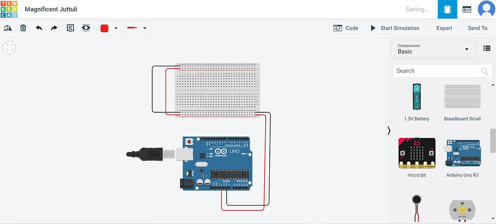
The breadboard is now connected to the Arduino Uno and ready for use. This set-up will be used as a basis for all the four activities.
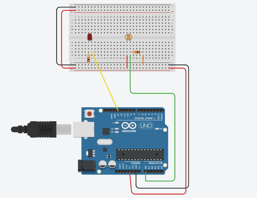
Interface Potentiometer Analog Input to Maker Uno board and measure its signal in serial monitor Arduino IDE
This activity allows us to read a variable resistor which this case is a potentiometer.
Add a LED light anywhere on the breadboard.
Attach a wire on any of the holes in the same row as the anode of the LED to Pin 13 and a resistor to any of the holes in the same row as the cathode of the LED to the ground. The resistor limits the amount of current going to the LED to prevent it from fusing. This whole set-up gives an electrical connection.
3. Add a Potentiometer to the the breadboard (horizontal to the LED) and wire the outer pins to power and ground, and the center pin to Arduino pin A0. Pin A0 is the analog input which senses the gradually changing electrical signals from turning the Potentiometer.
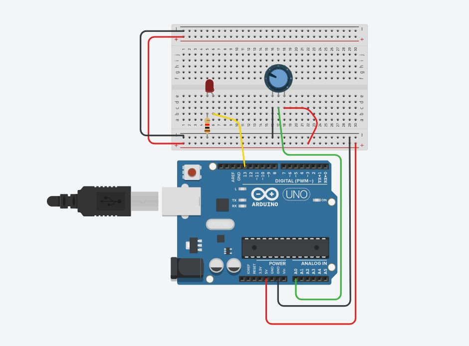
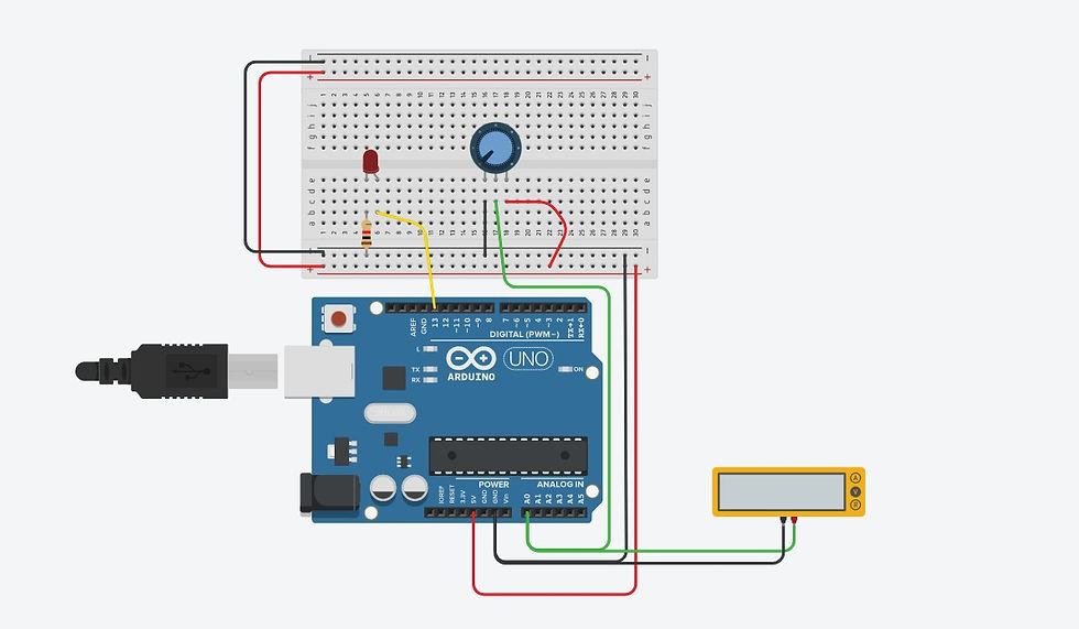
4. We will now connect the multimeter to Arduino Uno for measurement of signals. The positive terminal of the multimeter is connected to pin A0 while the negative terminal is connected to GND.
For the source code, we created a new variable, sensorValue. This variable stores the values read from my sensor. In the input category, we put 'read Analog pin' which converts the input voltage range, 0V to 5V, to a digital value between 0 to 1023. For the output category, we set the built-in LED to HIGH and LOW. In between the HIGH and LOW output, we used sensorValue to set a delay() of milliseconds. This makes the LED to turn on, waits between 10 to 1023 milliseconds before turning off, and the cycle repeats.
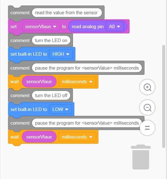
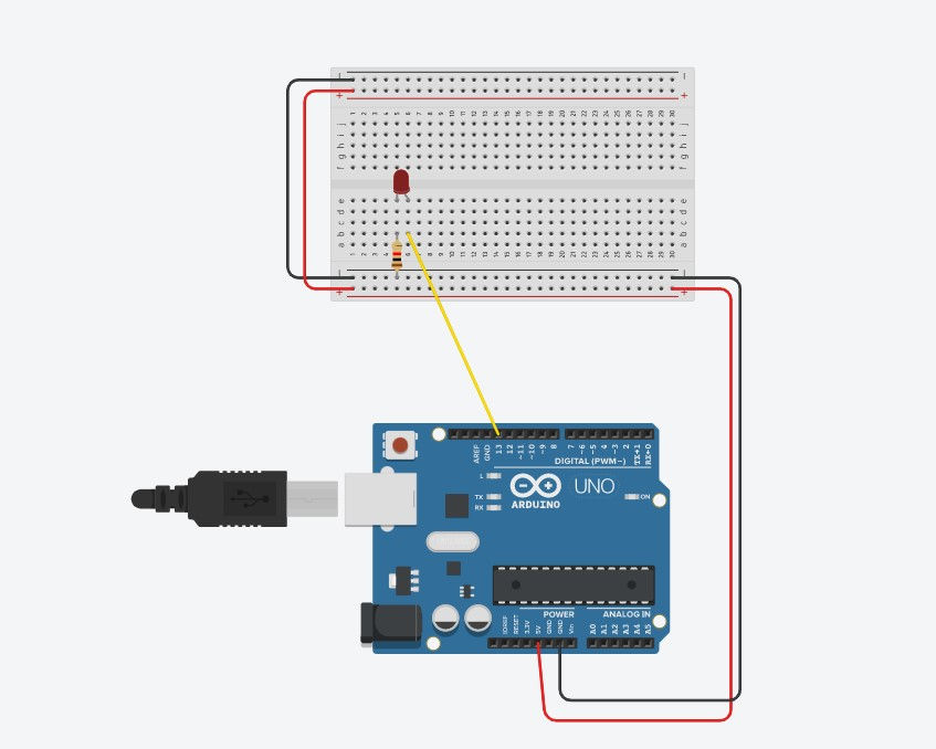
Below is the completed activity 1.
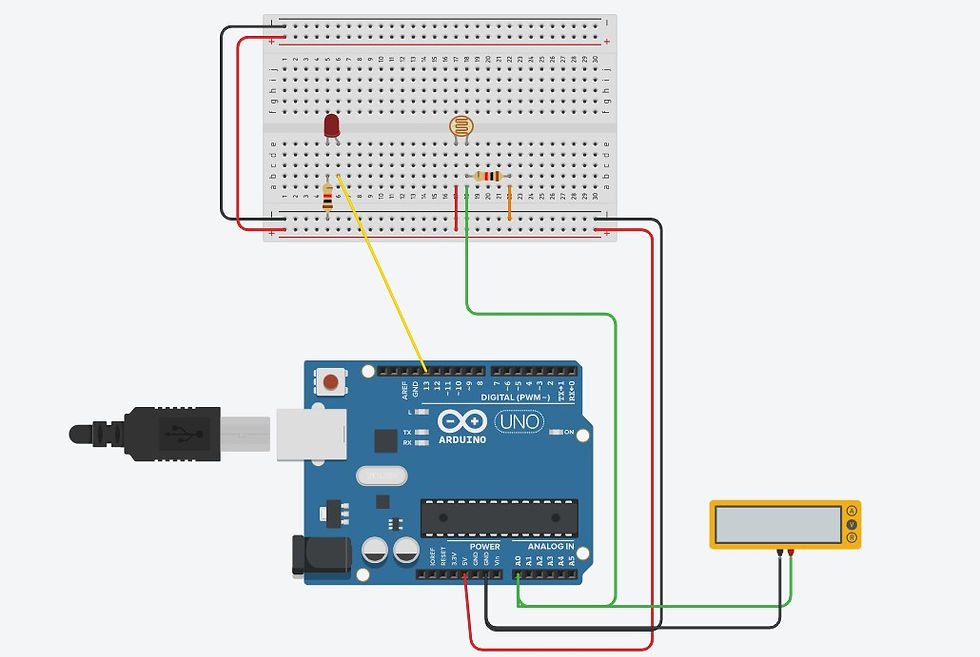
Interface a LDR to Maker Uno board and measure its signal in serial monitor Arduino IDE
An LDR (Light Dependent Resistor) is a component that has variable resistance that changes with light intensity that falls upon it. The greater the voltage, the greater the light. In Tinkercad, a LDR was referred to as a Photoresistor.
Add a LED light anywhere on the breadboard.
Attach a wire on any of the holes in the same row as the anode of the LED to Pin 9 and a resistor to any of the holes in the same row as the cathode of the LED to the ground. This gives an electrical connection.
3. Add a Photoresistor to the the breadboard (horizontal to the LED). Wire terminal 1 of the Photoresistor to the power on the breadboard (positive terminal) and connect terminal 2 to A0 on the Arduino Uno board. Pin A0 is the analog input which senses the gradually changing electrical signals from dimming and brightening the Photoresistor.
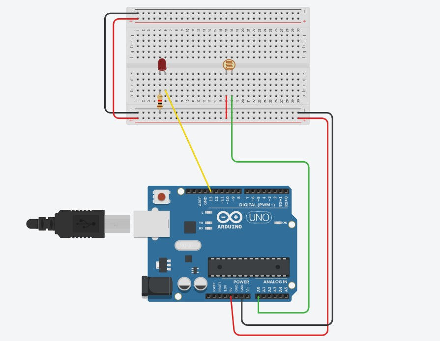
4. Take a resistor and turn it horizontally and plug that into any hole in the same row as terminal 2 of the Photoresistor, above the wire, and connect the free side of the resistor to the ground on breadboard.
5. Connect the multimeter to Arduino Uno for measurement of signals. The positive terminal of the multimeter is connected to pin A0 while the negative terminal is connected to GND.
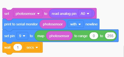
For the source code, to store the value of the photoresistor, I created a new variable called, photosensor. Set the photosensor to read analog pin A0. This is the input which converts the input voltage range, 0V to 5V, to a digital value between 0 to 1023. For the output, we print to serial monitor photosensor with newline. This enables the circuit to be able to send messages from the Photoresistor to the LED, and this provides the communication channel. In this case, it take 9600 bits per second for the speed of communication. Afterwards, we insert another output signal of set pin 9 to map photosensor to range 0 to 255. This is the range that the LED works. We then add a delay of 1 second.
Below is the completed activity 2.
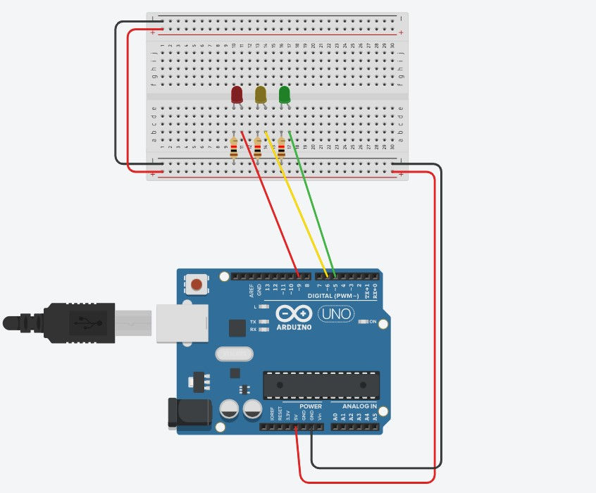
Interface 3 LEDs (Red, Yellow, Green) to Maker Uno and program it to perform something (fade or flash etc)
For this activity, we made use of the pins with a tilde (~) to compose a simple program to fade the LED brighter and dimmer. However, instead of using one LED, we used three, just like a traffic light!
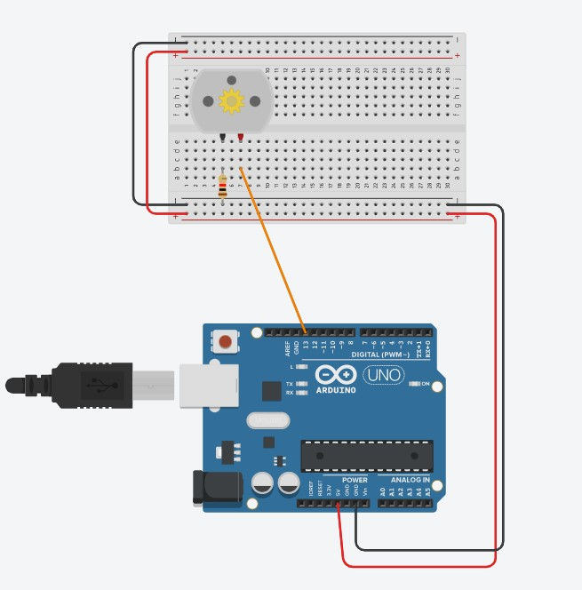
Add 3 LED lights anywhere on the breadboard, all beside each other. Choose the colours of the 3 LED lights to be red, yellow and green.
For each LED, attach a wire on any of the holes in the same row as the anode of the LED to Pin ~9, ~6 and ~5 respectively, and a resistor to any of the holes in the same row as the cathode of the LED to the ground. This gives an electrical connection and the finished set-up for this activity. We can now move onto the coding.
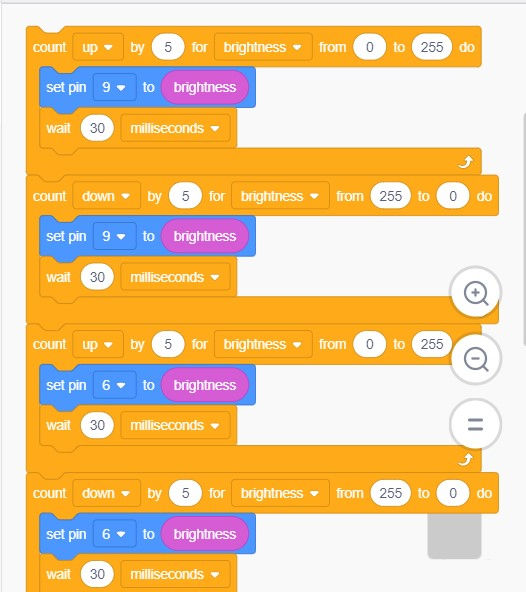
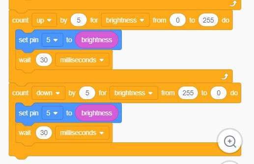
For the source code, I started off by control which count up by 5 for brightness (variable) from 0 to 255. 0 to 255 is the minimum and the maximum analog output value to fade a LED. For the output, I set 9 to brightness and added another control to wait 30 milliseconds. This makes the red LED, since it is connected to pin ~9, to fade up and go back to zero, over and over again. In order to make it fade out, there needs to be another counting loop, counting down from 255 to 0. I then repeated the two counting blocks for pin ~6 and ~5.
Below is the completed activity 3.
Interface the DC motor to Maker Uno board and program it to on and off using push button on the board
In this last activity, we had to create a breadboard circuit and compose a program to read a button and control a DC motor. When the button is pressed, the DC motor moves and when released, it stops.
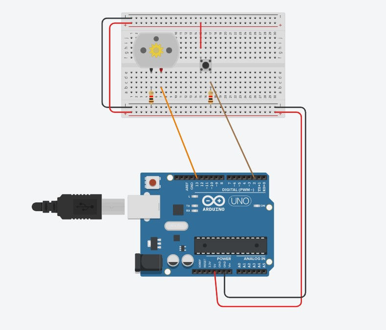
Add a DC motor anywhere on the breadboard, and wire terminal 2 to pin 13 on the Arduino Uno board and a resistor to any of the holes in the same row as terminal 1 of the DC motor to the ground.
2. Add a pushbutton to the breadboard, straddling the center divide. For this pushbutton, we will be wiring the two legs of the pushbutton diagonally.
3. Connect terminal 1b to 5V on breadboard and terminal 2a to Arduino Uno board pin 2. That way when the button is pressed, an electrical connection is made between power and the Arduino kit.
4. I also added a 10 kilo-ohms resistor between the Arduino pin and ground. This is called a pulldown resistor which gives the Arduino pin a weak ground connection, so the pin is never floating.
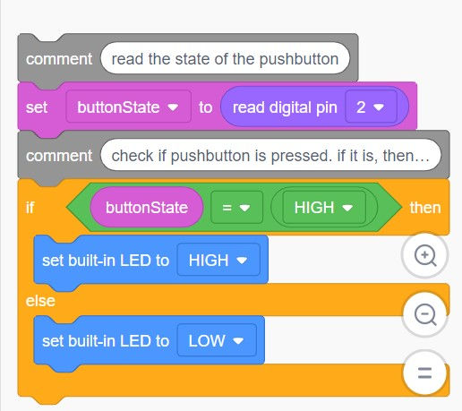
For the source code, I first created a new variable called buttonState. In the input category, read digital pin 2 was used. This reads the button state. I then used a math comparator block to evaluate whether the button state is equal to HIGH. buttonState should be equal to HIGH since the DC motor will be moving when the button is pressed. For the output category, I set built-in LED to HIGH and set built-in LED to LOW. This commands the DC motor to move when the pushbutton is pressed and not when released.
Below is the completed activity 4.
Through the first two activities on interfacing an input device, I learnt about the difference between an analog pin and digital pin. An analog pin is one that can read signals from a range of 0 to 1023 while a digital pin can only read signals pf HIGH and LOW which is essentially just ON and OFF. For the two input activities we did, we used an analog pin as both the Potentiometer and Photoresistor has a range of resistances from none to some maximum value. That is an analog device which needs to be connected to an analog pin.
And through the last two activities on interfacing an output device, I learnt about the reason for the addition of tilde (~) on certain digital pins on the Arduino Uno board. These pins include, ~11, ~10, ~9, ~6, ~5 and ~3. These pins are the same as the other pins with no tilde but they can also be used for Pulsed-Width Modulation (PWM). PWM is the output used for analog input which acts as a digital-to-analog converter. This helps to simulate analog output like fading an LED in and out.
Even before starting on the 4 activities, I faced a problem of not understanding what the activities meant. I did not know what a Potentiometer and LDR were nor did I understand why it was separated between input and output, when any system would have both an input and out output either ways. This problem was quickly resolved when I watched the videos provided for us and and lesson tutorials in Tinkercad itself, which were both very informative. Through the videos, it explained to me what a Potentiometer and LDR, guiding me step-by-step how I can incorporate these variables into the the electrical circuit. I also realised that the activities were categories into input and output while executing them, as the first two requires us to vary the input signals to achieve its corresponding output signals. On the other hand, the last two has varying output signals on a single input signal.
REFLECTION:
As a whole, this was my first time using both Arduino Uno and Tinkercad. I had never done anything remotely similar to programming nor have I imagined that I would find it enjoyable. But to my surprise, it was a lot easier and entertaining to use both the Arduino Uno and Tinkercad.
Initially, it was extremely frustrating to code the Arduino Uno as I did not understand what the symbols, words and acronyms meant. So, it often led me to writing in the wrong sequence or missing out a symbol since I was copying blindly from what was given to us in the Arduino Uno learning package. What frustrated me the most were the punctuation marks. I had to care about all the small details of the coding and when the punctuation marks were incorrect, the code would not upload to the Arduino board. The two most important punctuation mark that felt important to me were, ; which was to be input after every action command, and {} which starts and completes the coding. However, once I understood the pattern of coding, everything else was mostly smooth sailing.
This individual activities using Tinkercad allowed us to be more familiar with the other components of the Arduino Uno kit that we did not get to use before and how to use them properly. Some of these include the breadboard, LED, resistor, DC motor and LCD. I feel that Tinkercad was useful for introducing these items as they require electricity. If we were to do it straight at the physical Arduino Uno, and we messed up, making us try repeatedly, we could overheat the circuit causing the whole programming to fail. Hence, Tinkercad was a good way of letting us experiment with all these features without the fear of messing up the Arduino Uno board. Through these activities, I learnt that a breadboard needs power in order for it to work as it is a solderless construction base. This power can be achieved through connecting the breadboard to GND and 5V on on the Maker Uno board which was a fascinating to me as I thought that we would need to connect to a separate battery. This made me realise how smart and efficient this Arduino Uno kit was.
All in all, I feel that I was taken away an important skill that is very relevant to this fast-changing world, where IT is revolutionary. Even though I was only introduced to the basics of programming, I feel like this set a good basis to further building on my skill and just being introduced to what programming is in general. This skill will also benefit me in my future CPDD journey. As we progress in this CPDD module, we would eventually have to make our chemical product and with this programming abilities, we can actually make it work and automate, not just displaying its shell, by giving it input and output instructions through programming. This contributes greatly into making our project complete and I plan to use this newfound skill wisely in my CPDD journey and in my future projects I will be undertaking.


Comments