3D PRINTING
- sjhyun20
- Dec 27, 2021
- 8 min read
This CPDD assignment is all about 3D printing!!!!!!!!!!! We had to design a model in Fusion 360 and export to Cura to print it using the school's 3D machine.
First on this assignment, design an object that cannot be made substractively. So, what does cannot be made substractively mean? It basically means to fabricate something that cannot be easily made by hand due to multiple parts involved during the manufacturing process. After much consideration, and going through multiple YouTube videos, I decided to designing a ball bearer.
The ball bearer cannot be made substractively because in order to create this by hand, I need to create two rings, multiple balls and a cage, while is shaped like a cookie cutter to hold the balls together. After making all these components, we still need to assemble it together. This will be a very tedious process, if I make it by hand. It will also not be easy to fabricate the cage. However, this process will be much easier when 3D printing, as it will print everything I designed of the ball bearer in one shot, without me having to print each component separately and assembling them together.
To design this ball bearing, I followed a YouTube video tutorial by Ansys Gladiator (https://www.youtube.com/watch?v=7sW4JcOYdB0&t=20s).
Here are the steps on how I designed it on Fusion 360:
1. Select the right plane and use the Center Rectangle to create a rectangle with the dimensions 25mm by 7.5 mm.

2. Create the same rectangle as step 1, below the first rectangle. Then, use the Sketch Dimension feature. Click on the center of both rectangles and put it to be 20mm.

3. Click on the Centre Circle and create a circle in between the two rectangles, with a diameter of 17.5mm. Then use the Sketch Dimension feature to ensure the center of the circle and the center of the bottom rectangle are 10mm apart.

4.Use Line to create a line from the top of the circle to the bottom of the circle. Afterwards, Sketch Dimension the top of the first rectangle to the red line of the Fusion 360 background to be 60mm. These are the two rings of the ball bearing.

5. Finish the sketch. You will get something like this:

6. Use Revolve to click on the two rectangle and select the right bottom corner plane (indicated by the green line of Fusion 360) to achieve the 3D model of the two rings.
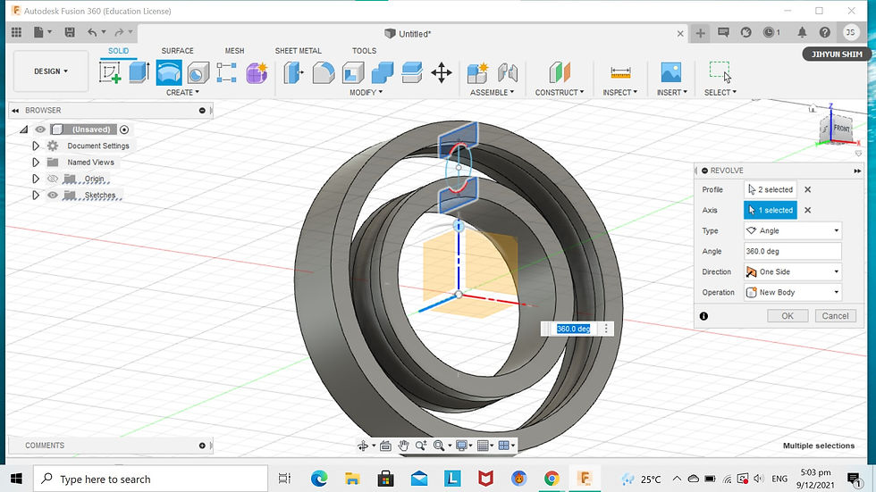
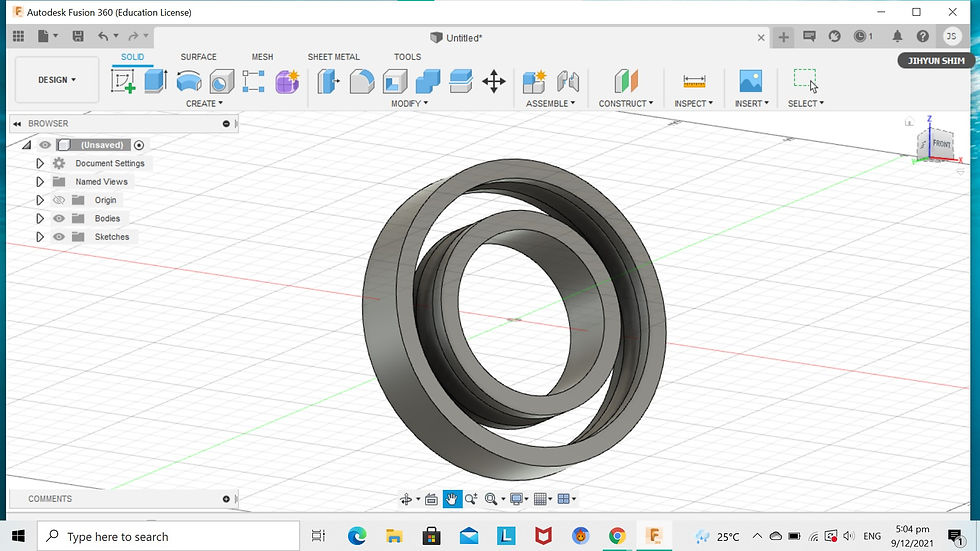
7. Reveal Sketch 1 and use Revolve and click on half the circle and select the right-side corner plane (indicated by blue line on Fusion 360) to achieve one ball inside the two rings.

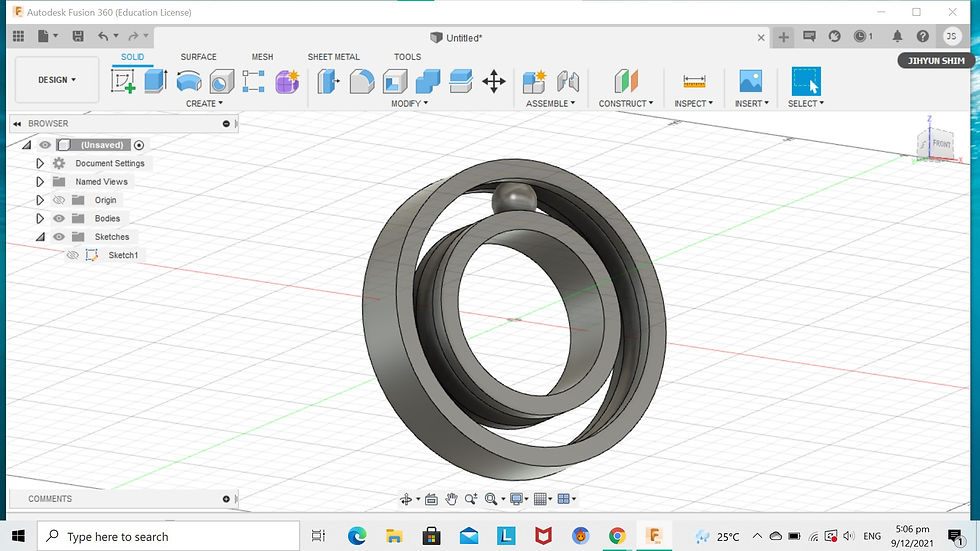
8. Hide the sketch. Use Circular Pattern to duplicate 13 balls inside the rings. The plane to be selected in the right bottom corner plane (indicated by the green line on Fusion 360). In total, there should be 14 balls.


9. Create a new sketch, this time using the front plane. Use Center Circle to create two circles with the dimensions 90mm and 97mm respectively. Finish the sketch. This is the sketch for our cage.

10. Use the Extrude feature to click on the new sketch and the circular ring from sketch 1, and put it to be 12.5mm.

11. Once you confirm the previous step, it can be noticed that the 3D model of the cage is outside the balls. To put this back in, click on the extruded cage and put it to be -12.5mm. It can be observed that the cage fits nicely around the balls, between the two rings.
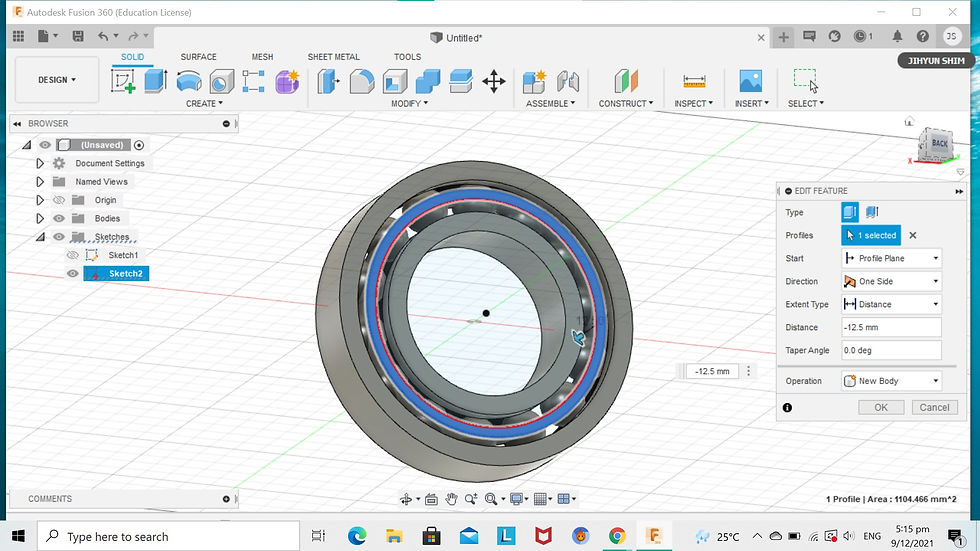
12. Hide bodies 1 and 2. Then, click on Combine and select the cage and the 14 balls. Press OK.
13. Hide the 14 balls. Use the Shell feature and select the outer, inner and bottom of the cage, and change the inside thickness to be 1mm.
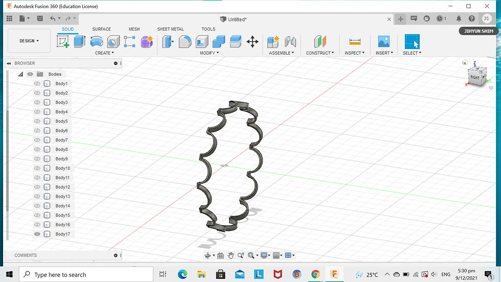
14. Use the Mirror feature to select the cage and the right plane to obtain the full cage.

15. Unhide all the bodies and the designing of the ball bearing is complete. Below is the final sketch of the ball bearing.
Now that the designing of the ball bearing is all complete, we can continue on to export this to Cura and prepare it for 3D printing.
To export the design to Cura, we need to save it as a STL file. We can do this by right-click the title of the file and select Save as Mesh. From there, we can format the file to be saved as a STL file. There were two options for STL, but STL (Binary) was chosen. Binary files are smaller and easier to share so it is recommended for 3D printing, where the file has to be exported from places to places.


This the STL (Binary) file:
Once I saved the STL file, I located the file on my laptop and opened it. Since I already had Cura downloaded on my laptop, the file opened immediately to Cura.
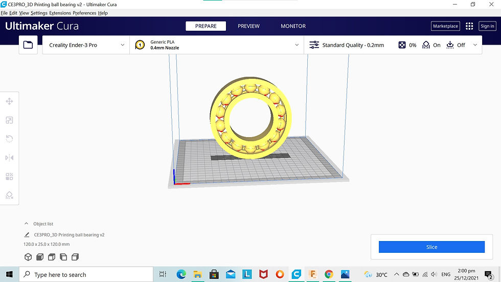
Before I went on to adjust the print settings, I rotated my design to lay flat on the machine. Ctrl + A to select the whole design on the Rotate icon, followed by the Lay Flat icon. Use the green arrow to make the design horizontal and the design will lay flat on the machine nicely. We have to ensure the design is nice and flat on the machine ground so that the printer can start the manufacturing process with a solid base that properly adheres to the print bed.
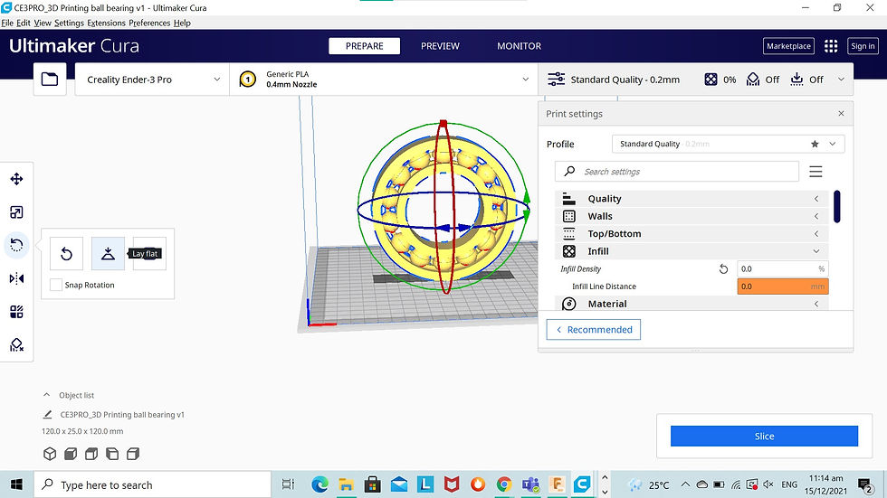
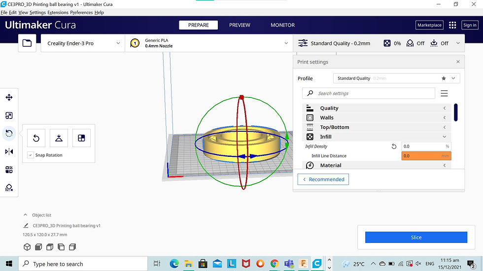
I can now begin my 3D printing process. First, verify that Creality Ender-3 Pro is chosen for the printer model and 0.4mm Nozzle is chosen for the Generic PLA. Second, adjust the print settings.
Multiple tries were taken to achieve the most ideal settings. The 3 mains components to be adjusted are Infill density, Speed, Support and the Scale. Infill controls the amount of fill in the internal cavities. The flatter the design the less infill required. Higher infills give more strength, but longer time to print. Speed is time taken for the printer to print the 3D model. For this printer, it has a maximum of 100 mm/s. Supports are used to aid the printing of overhangs. Overhangs are designs that are "floating on air". Supports add to the print time as well as the touch-up and finishing time to the model, but it makes impossible parts to be printed and can be removed after the prints are completed. Support has a maximum overhang angle of 45° of vertical line. Scale is the size of the 3D model. It can be decreased to reduce the printing time.
On my first try, I only increased the infill and speed to 20% and 80mm/s respectively. However, when I sliced it on Cura, nearly 7 hours were needed to print the model.
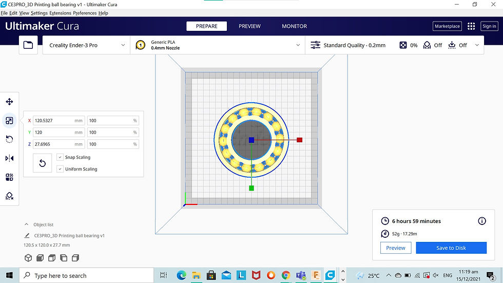
After consulting the lecturers, it was concluded that the size of my model was too big, thus it was taking a very long time to print. I was also told that my model does not require infill. So, for my second try, I decreased the infill to 0% and scaled down to 20%. This made my design to be too small, merely taking 16 minutes to print.

I then increased it in increments of 10 until I reached a size that was satisfactory, with a reasonable printing time. The final scale size was 40% with 1 hour and 2 minutes of printing time. The picture attached below shows the final print settings.

With all the adjustments of the print settings complete, I went on to print the ball bearer. In order to do so, I converted the Cura file into a GCODE. This can be easily converted by saving to disk after slicing preview. The GCODE will be automatically generated when you Save to Disk. Through this experience, I realised it is essential to name the file that is easily recognisable to you and to remember what you named it as we are to save the GCODE on the SD card provided to us by the school and there are multiple GCODEs saved in it as well. I made the mistake of not remembering my GCODE name, and I printed the wrong model on my initial try.

Once the GCODE is generated and saved to the SD card, insert the SD card into the 3D printer and find the GCODE to be printed. Press Print, and the ball bearer starts printing. Below is a video process of the ball bearer being printed.
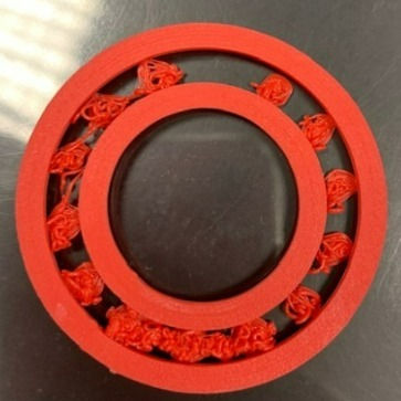
As I was printing the ball bearer, I realised something was odd. The balls were not nicely printed as a ball, but instead looked like a bunch of scrunched up ink. The cage was not even being printed.
Perplexed, I consulted the lecturer once more. Dr Noel pointed out right away that this was due to the lack of support for the balls and cage. Thus, I generated the support, which automatically set the support adjustments for me. I just had to ensure that the Support Placement was set to Touching Buildplate. Picture below observed are the support layers.
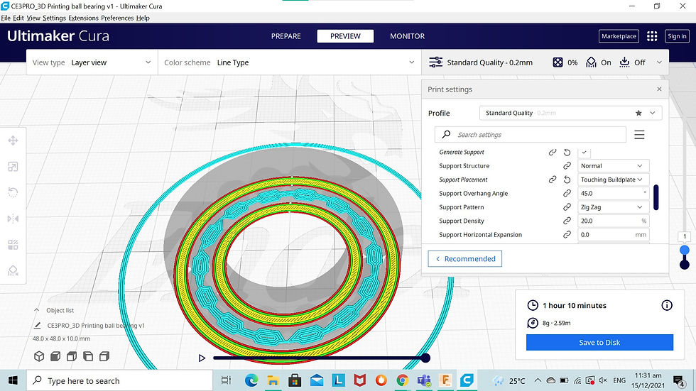
Support is needed for the balls and cage as they are placed above the ground, held together by the two rings. This gap between the printer base and the balls, which indicates the absence of a solid base, make it impossible for the printer to print nice layers for the balls and cage that are well-attached to the two rings. The support helps to secure a part of the printer bed for the balls and cage to be printer on. The support is removed using the tools provided once the printing is complete.
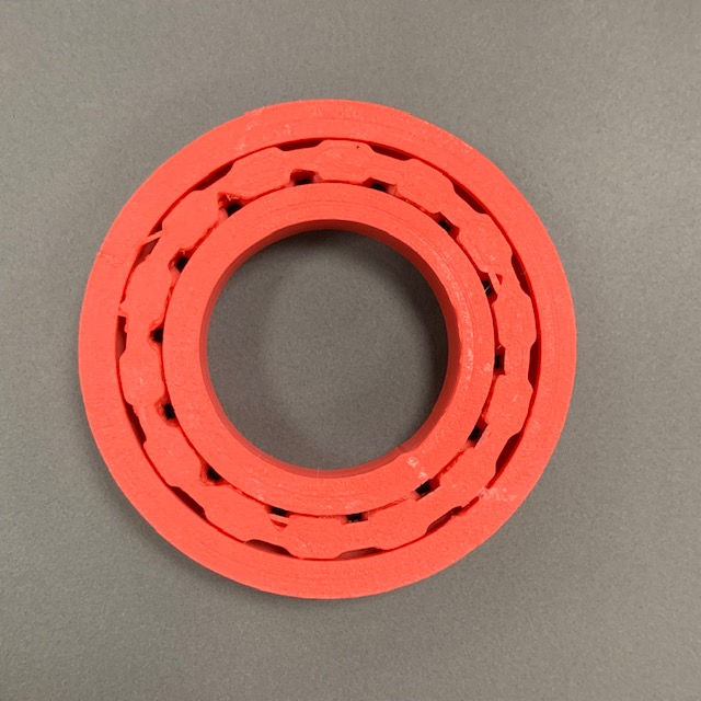
This the final printed ball bearer:


REFLECTION:
The first time I was introduced to 3D printing was in year 2 semester 1's Introduction to Chemical Product Development module. Back then, we were only thought on how to design a model in Fusion 360, but never got to print out the model ourselves using the 3D printer. Thus, this assignment was truly enjoyable to me and it felt like I was making up for lost time! I am also extremely satisfied with how my ball bearer turned out despite the multiple failed attempts I had, which ultimately led me to finding the most ideal adjustments.
This assignment was also a very independent learning experience for me as we had to find time during the holidays to complete the 3D printing and figure out what adjustments had to be done on Cura for a successful print. Every
time I faced a problem, I had to take initiative to consult a lecturer or browse through the BlackBoard notes given to us, and make the adjustments through trial and error. This made me take greater ownership of my work.
The main learning point I took away from this assignment is that we should observe the slicing steps in Cura with more detail. Cura is a powerful software that will generate adjustments and even gives us suggestions for the slicing to be done. If it suggests that a support is needed, a support should be added. In my case, even if the ball and cage where held together at the two ends by the rings, a support should still be used as it does not have a base to start slicing layers of the balls and cage. This brings me to how I should also be observing the first layer of the print more carefully. The first layer in the base to the following layers, affecting the final look of the 3D printed model. Instead to feeling accomplished that I started my printing, I should have watched how the printing goes in the beginning so that the moment I see that the ball was not being printed properly, I can stop the printing and make the necessary adjustments. If I had done this during my assignment, a lot of time could have been saved.
Moving forward, I will continue to use 3D printing in my CPDD journey, most probably using it to print parts that cannot be made substractively like hinges and clasps that our group will be using for the lid of the Handphone Sterilisation Box. These parts are essential in making our product successful as they are the ones responsible for ensuring our safety and maintaining our handphones in the best position for sterilisation to take place, adding the finishing touches to our product. Constructing these parts by hand may cause mistakes in measurements and accuracy, resulting in repeated attempts, wasting time.
All in all, I feel that 3D Printing is a very useful and powerful tool and skill to possess, being used functionally not only in our CPDD journey but also in our future projects such as our final year project.


Comments